Flying testbed: version 2.0
Before the New Year, on December 29 our rocket for testing the control system prototype made its flight. At Lin Industrial we traditionally call it "flying testbed", because the rocket has no independent value, but serves for testing the control system.
The rocket was not a modified old design, but an entirely new device. Among the conspicuous differences (except color, of course) — smaller cameras and tail section designed to contain four engines. Due to extra engines the testbed flight can last longer, therefore there is more time to validate the control system.
Today we publish an extended description of the "flying testbed" version 2.0.
So, this instance includes:
- tail section with rudder servos, grid fins and solid rocket motors;
- control system (CS) compartment including the CS itself, batteries, AltimeterThree device, GPS tracker, Arduino-based electronic unit, and two cameras on the outside of the compartment;
- front section with ogive shaped nose cone, ejection charge and parachute.
Tail section
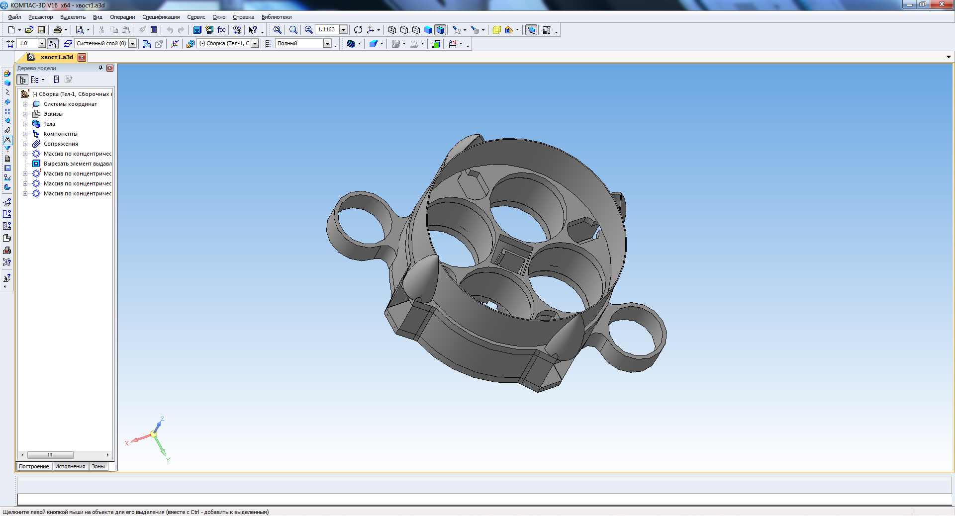
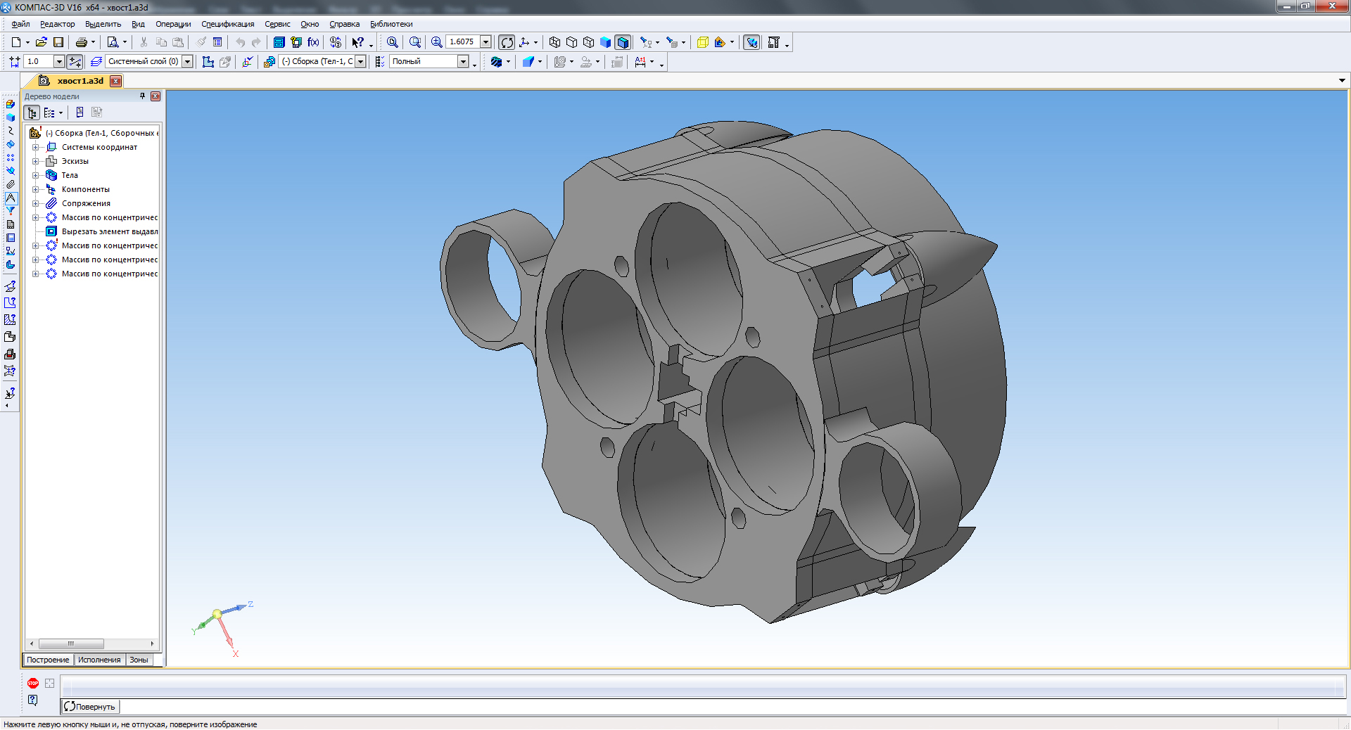
At the bottom end the tail section is terminated by the end frame. The frame was 3D printed.
Grid fins were also 3D printed.
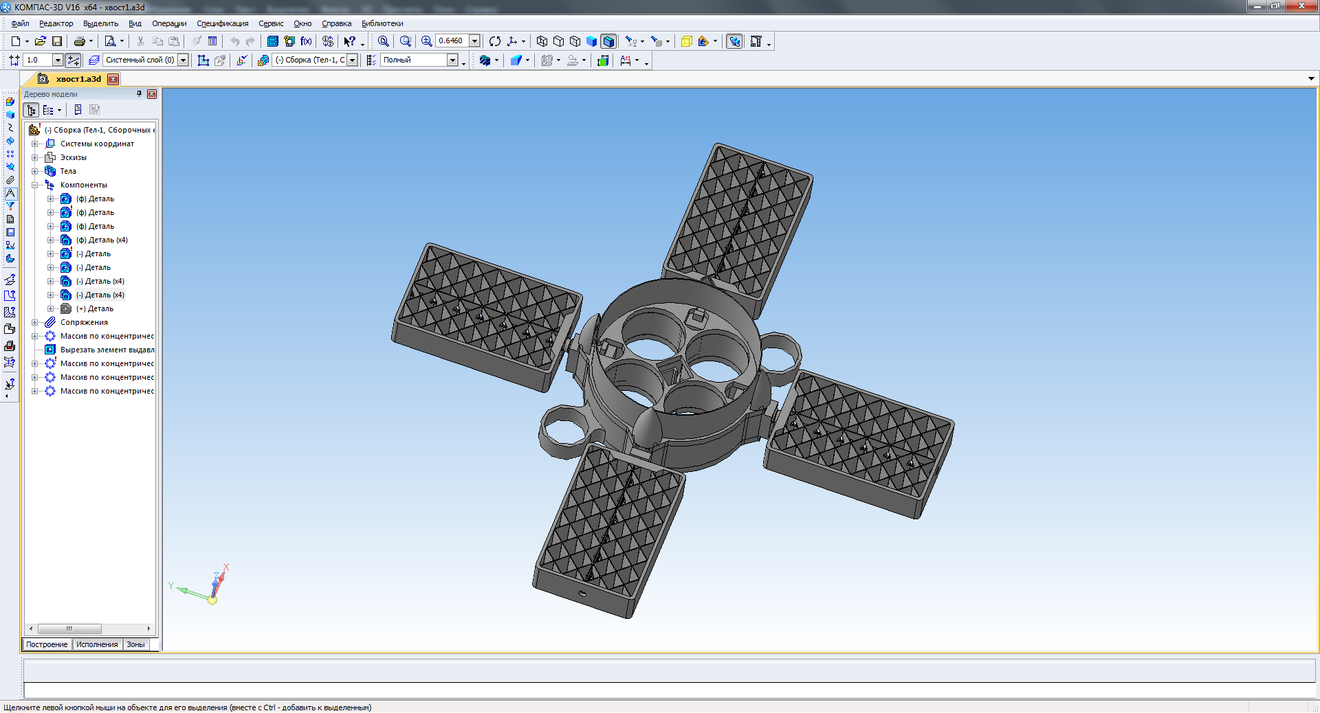
Printed grid fins:

A grid fin with attached rocker to be connected to rudder servos:
The gray end frame has slots for Real Rockets solid motors with a total impulse of 300 N•s each, chambers for servos and two rings for launch rails. Orange grid fins are attached to the servo drives. In the center of the frame there is a connector for igniters of the SRMs which are to be ignited in flight.
Fixing the end frame to the tail section of the rocket (wires are laid along the casing):
Tail section (top view):
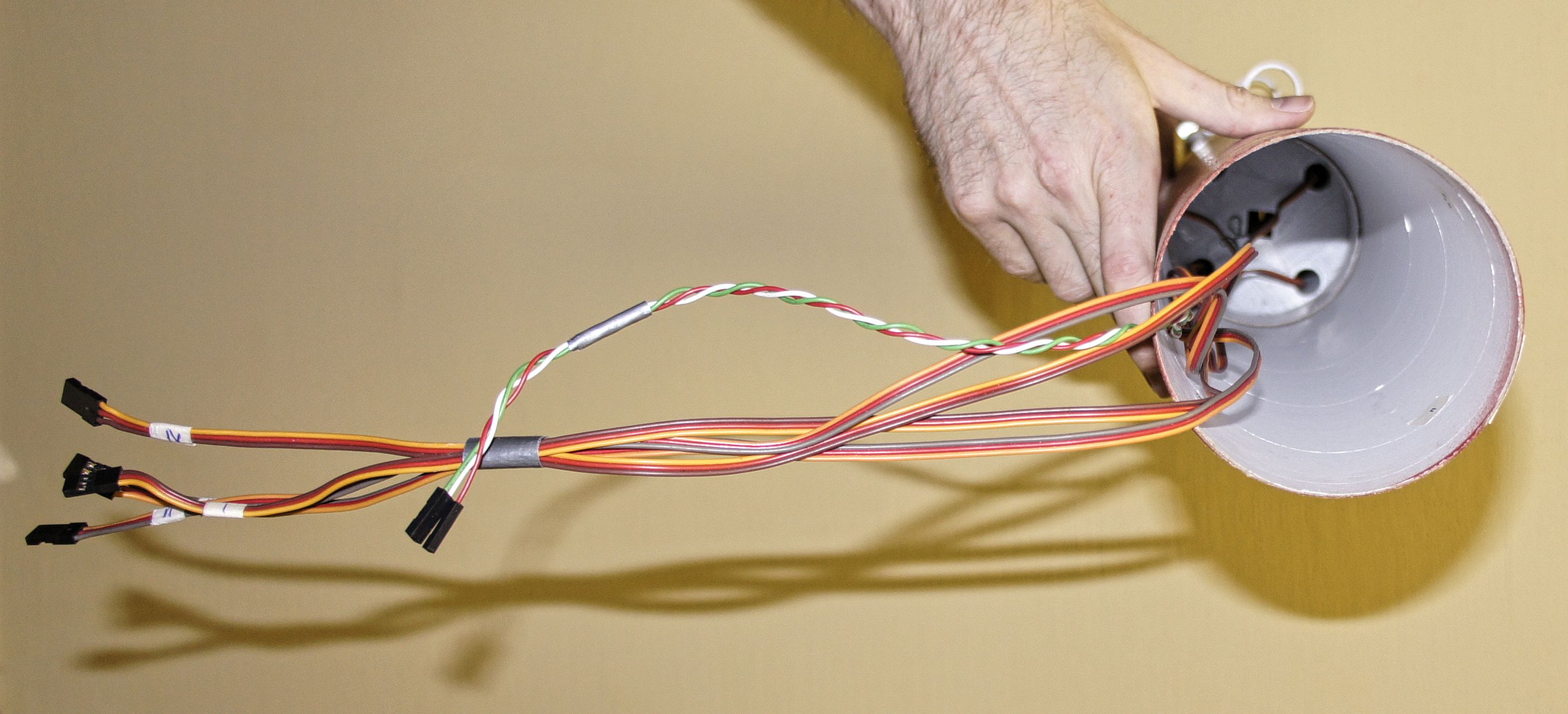
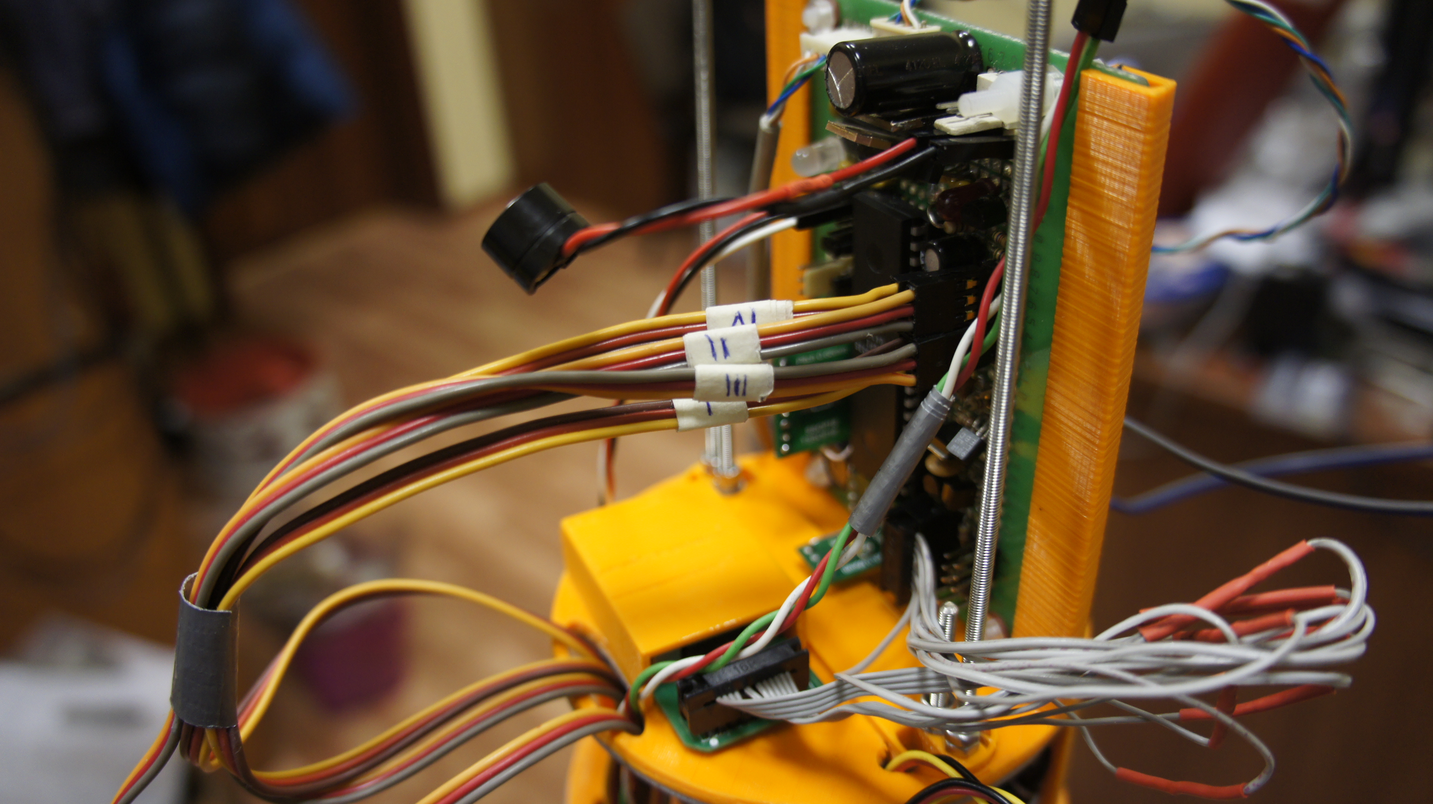
Wires from the servos are numbered and go to the top of the tail section. They are to be attached to the corresponding connectors on the CS board (shown later).
CS compartment
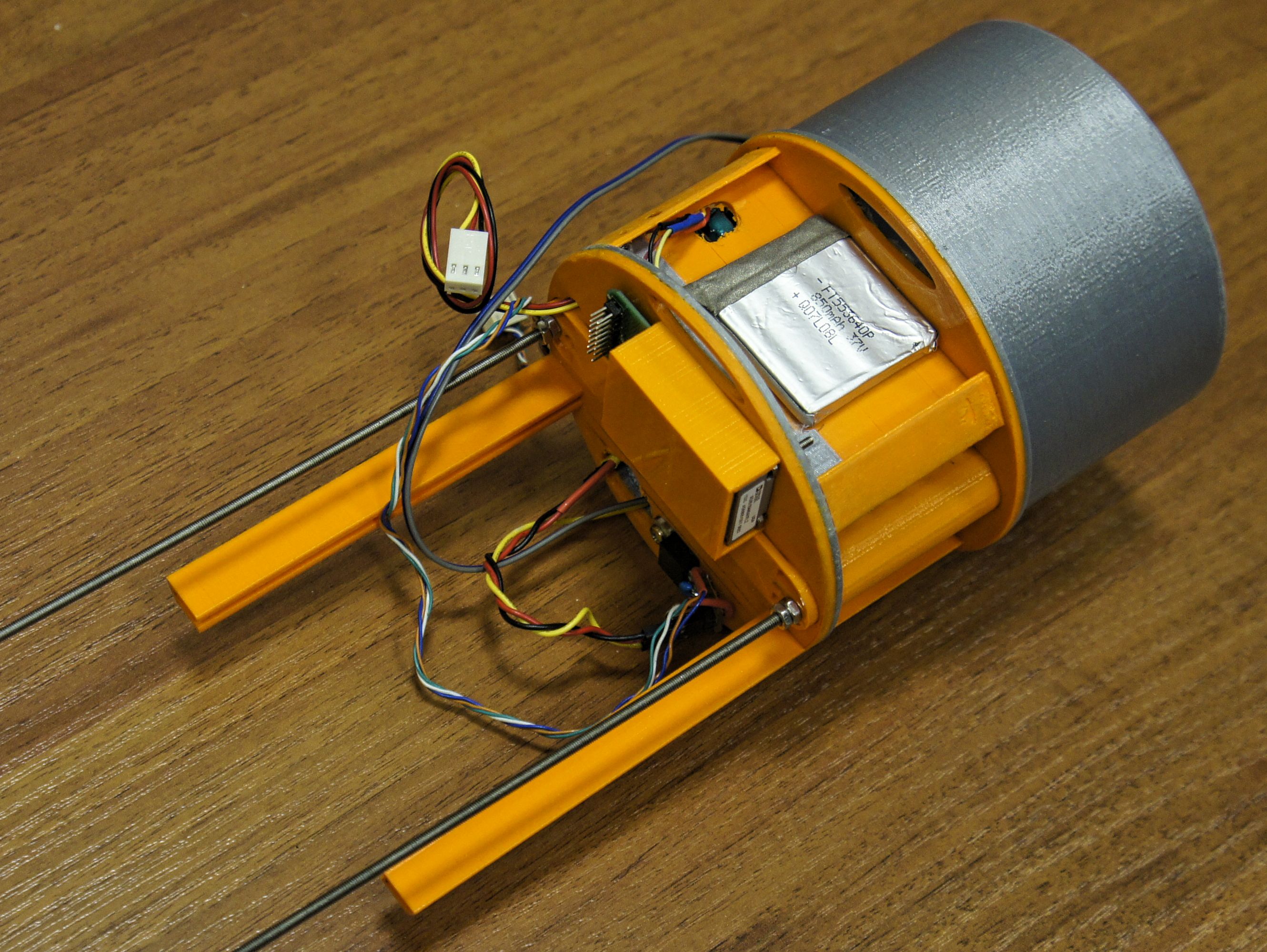
The CS compartment, with rods threaded through it, is to be inserted, gray side first, into the tail section of the rocket.
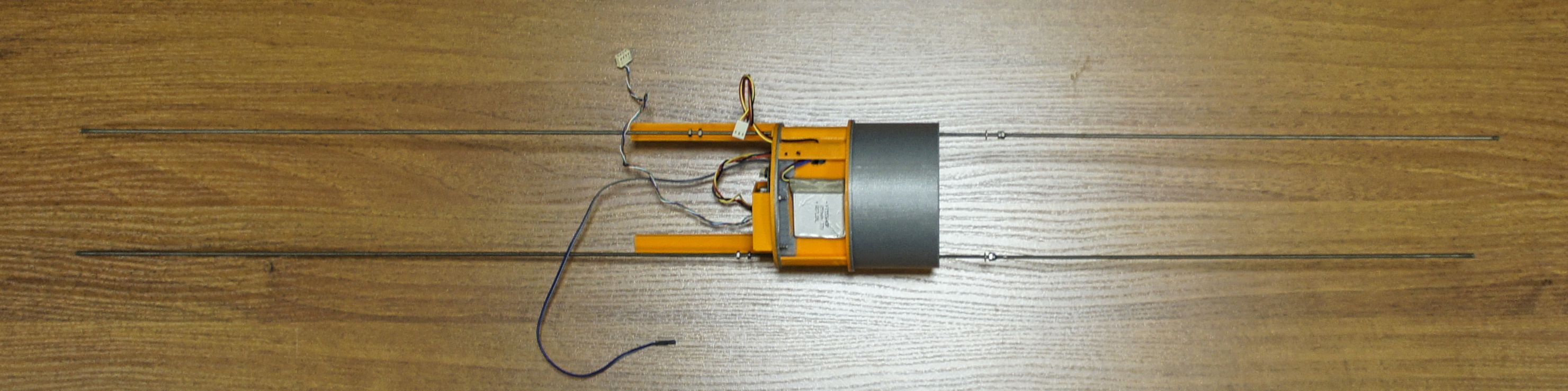
In the middle of the compartment there is a place for batteries. In the upper part there are rails for holding the CS main board.
The CS main board is inserted into the rails.
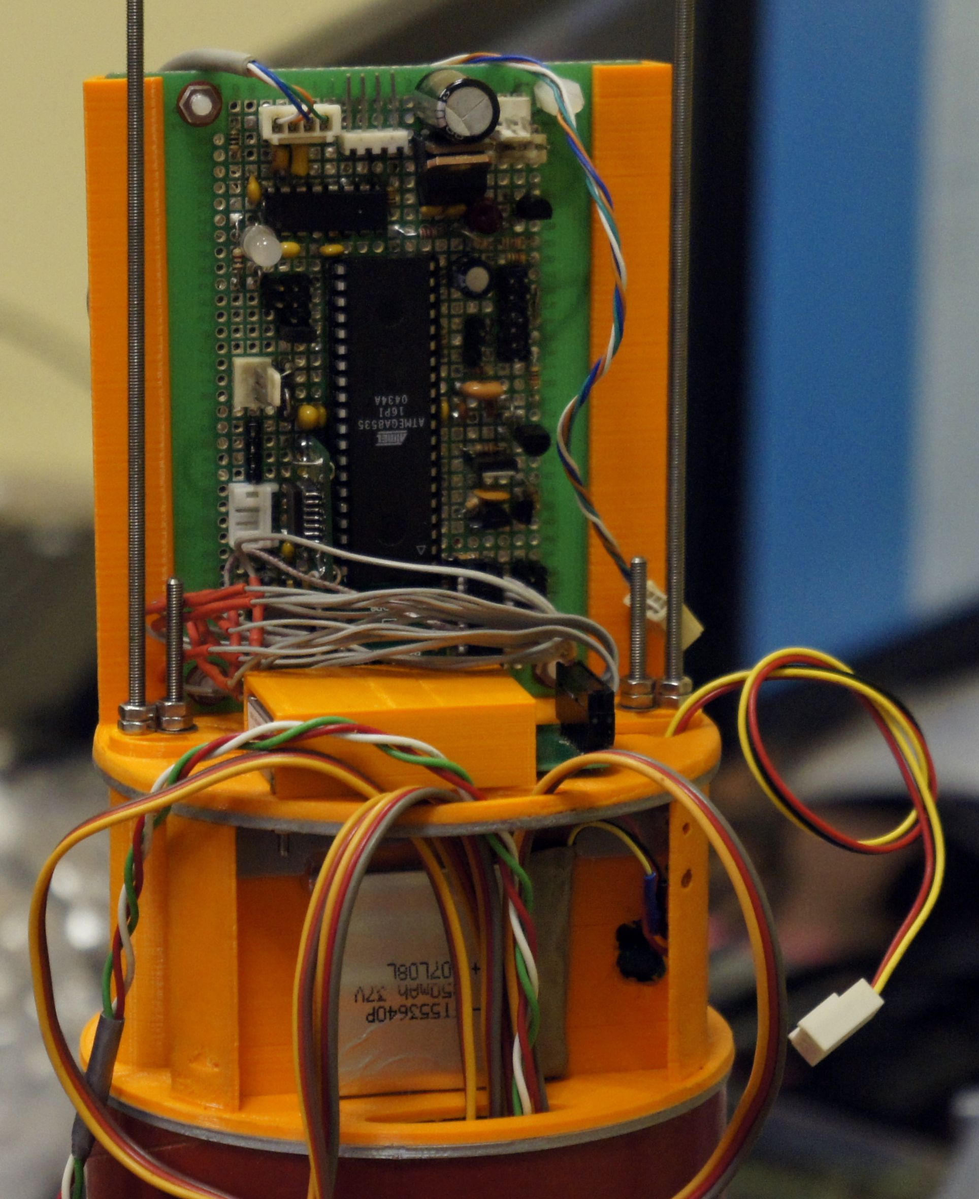
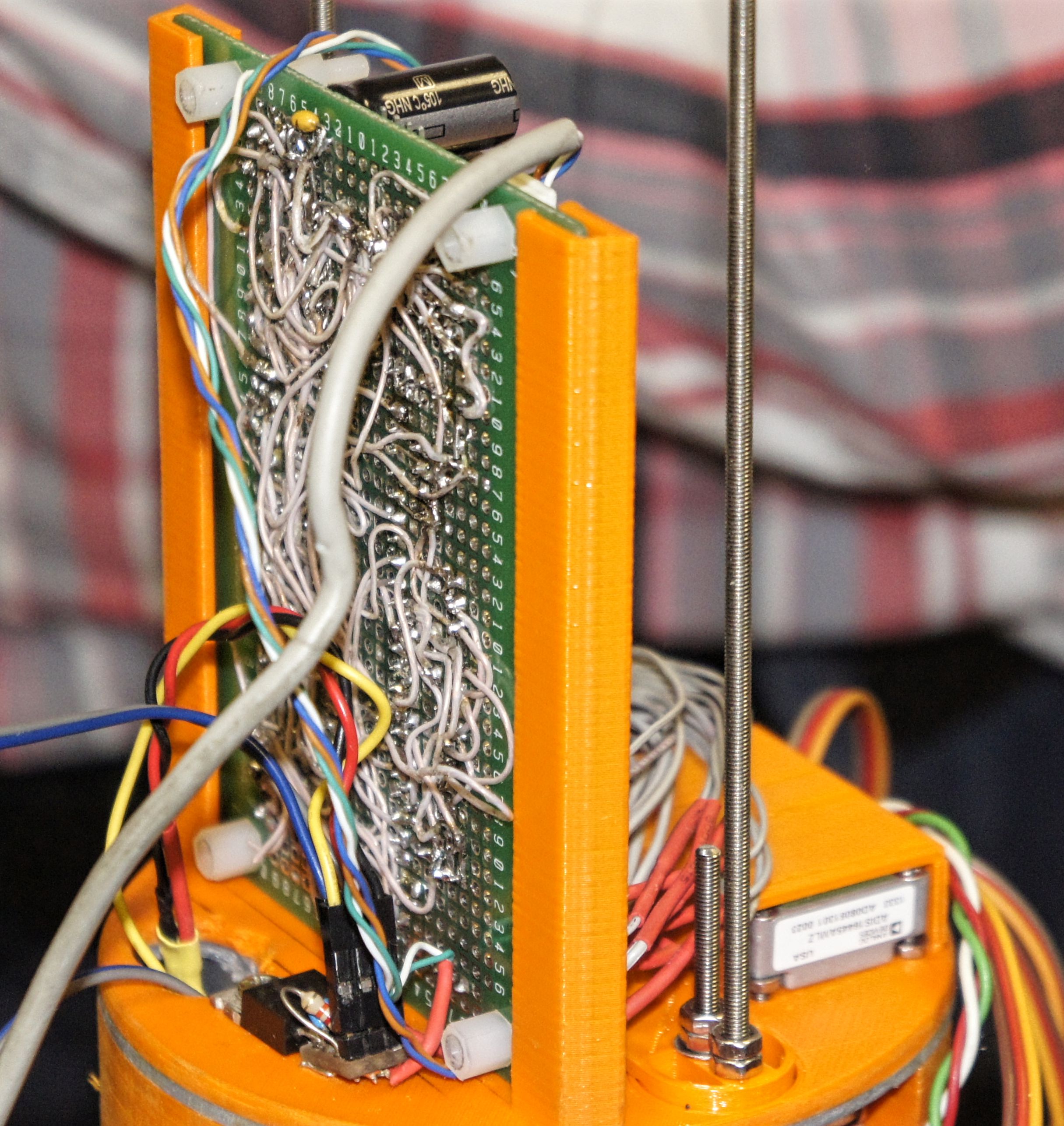
Cables from the igniters at the bottom are connected to the CS board. The cables are numbered:
The CS on the new «flying testbed» also differs from the one that flew in earlier rockets.
It is implemented on a new controller (ATmega8535 instead of ATmega8). Accordingly, the code was modified for the new controller. There are different signal processing algorithms in the new code (since the CS now doesn't directly control the electric motors turning the rudders, but controls the servos through their own electronics), while the former code fragment, controlling the motors directly, was dropped. The updated program can also deploy a parachute, record telemetry into the flash memory and monitor the CS health. The new system controls the rocket in all three axes.
The circuit diagram for the CS:
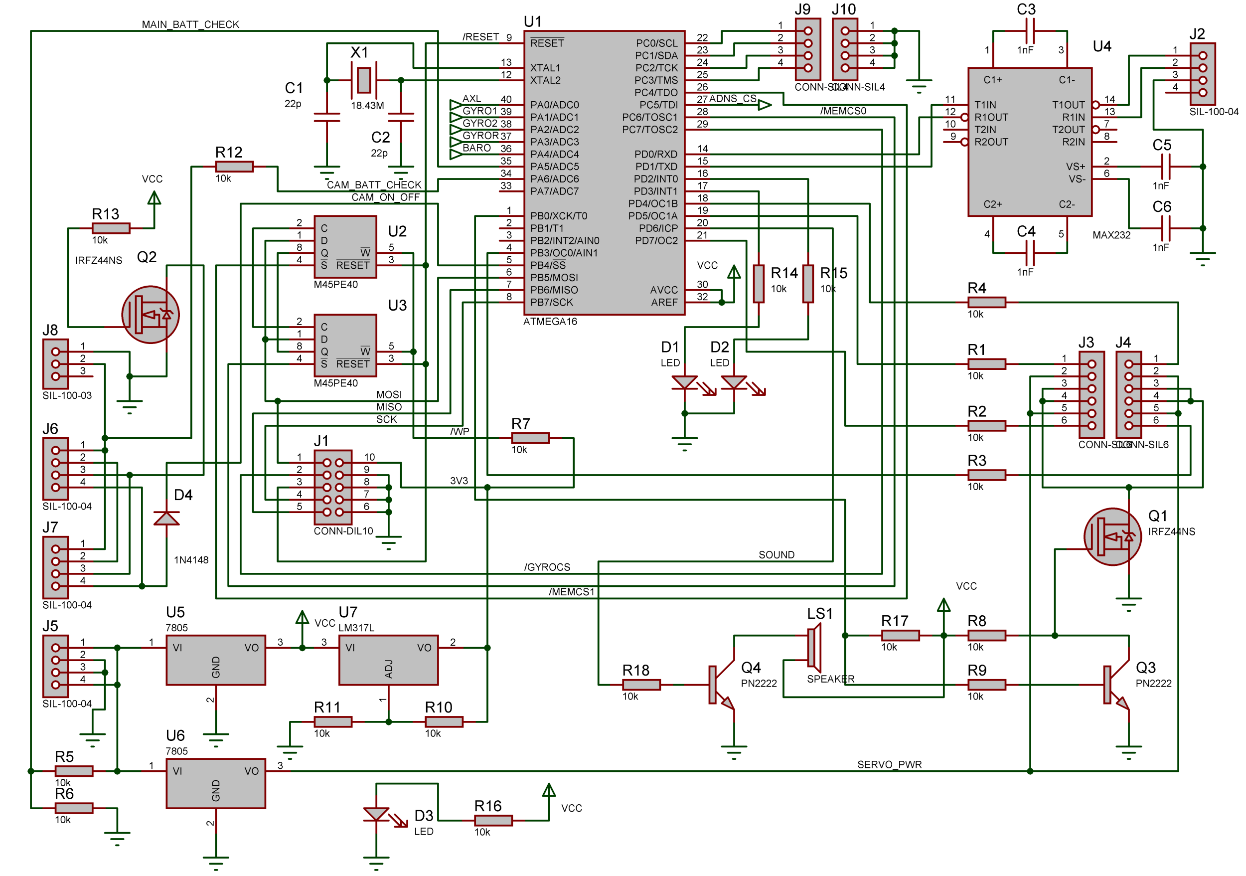
Note: the diagram doesn't include sensors (barometric sensor, external accelerometer, external gyroscope) and ADIS16445 chip (three-axis MEMS gyroscope + three-axis accelerometer); the controller is marked as ATMEGA16 — this chip was used in earlier designs of the CS and is pin-compatible with ATmega8535
Front section with CS compartment cover
The front section contains ogive shaped nose cone (orange colored) with parachute tied to it, which is ejected by means of activating a pyrotechnic charge (the charge is initiated by a command from the CS).
Pictured above is the front section with CS compartment cover docked to it (orange cylinder with cameras on the outside).
In addition to covering the CS compartment and holding the cameras on the outside, the cover has a number of devices on its top (this part is not seen on the photo, as it is hidden behind the red casing).
Below is the cover close-up without cameras (top of the cover, where AltimeterThree, GPS tracker, Arduino unit are nominally located):
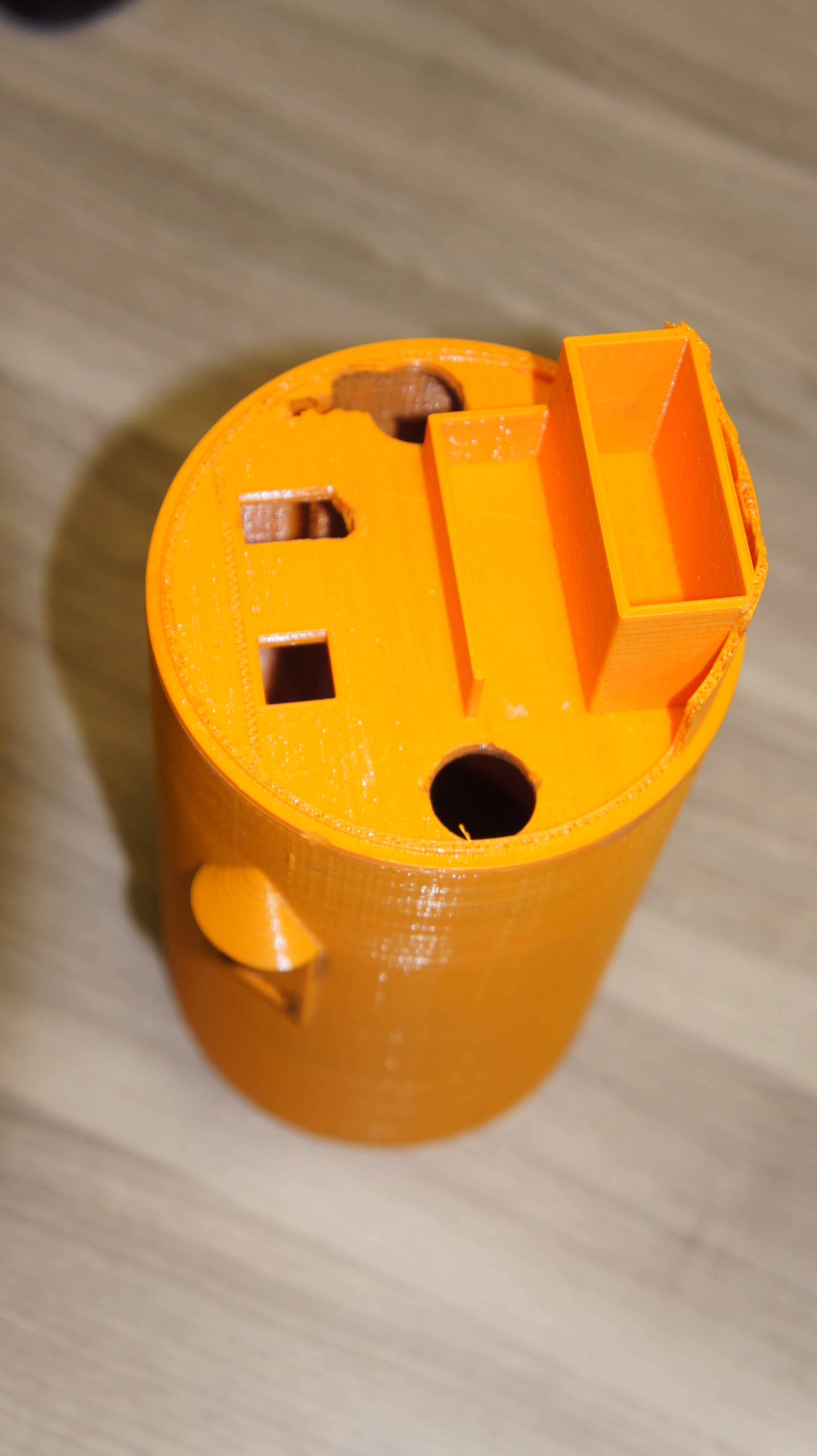
List of the devices located on top of the cover:
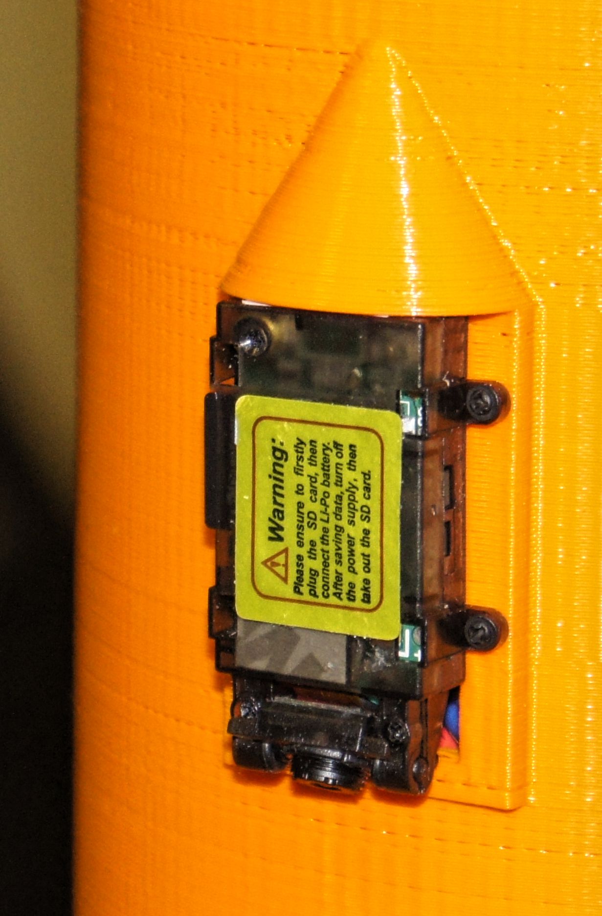
- two cameras powered by their own battery, but controlled by the CS (on the outside);
- Xexun TK102-1 GPS tracker, which can dump its coordinates via SMS;
- AltimeterThree device by Jolly Logic, which includes barometric altimeter and three-axis accelerometer, needed to verify the CS sensor readings;
- Arduino-based electronic unit, which can dump the GPS data via Wi-Fi.
Camera close-up (the second camera is located symmetrically):
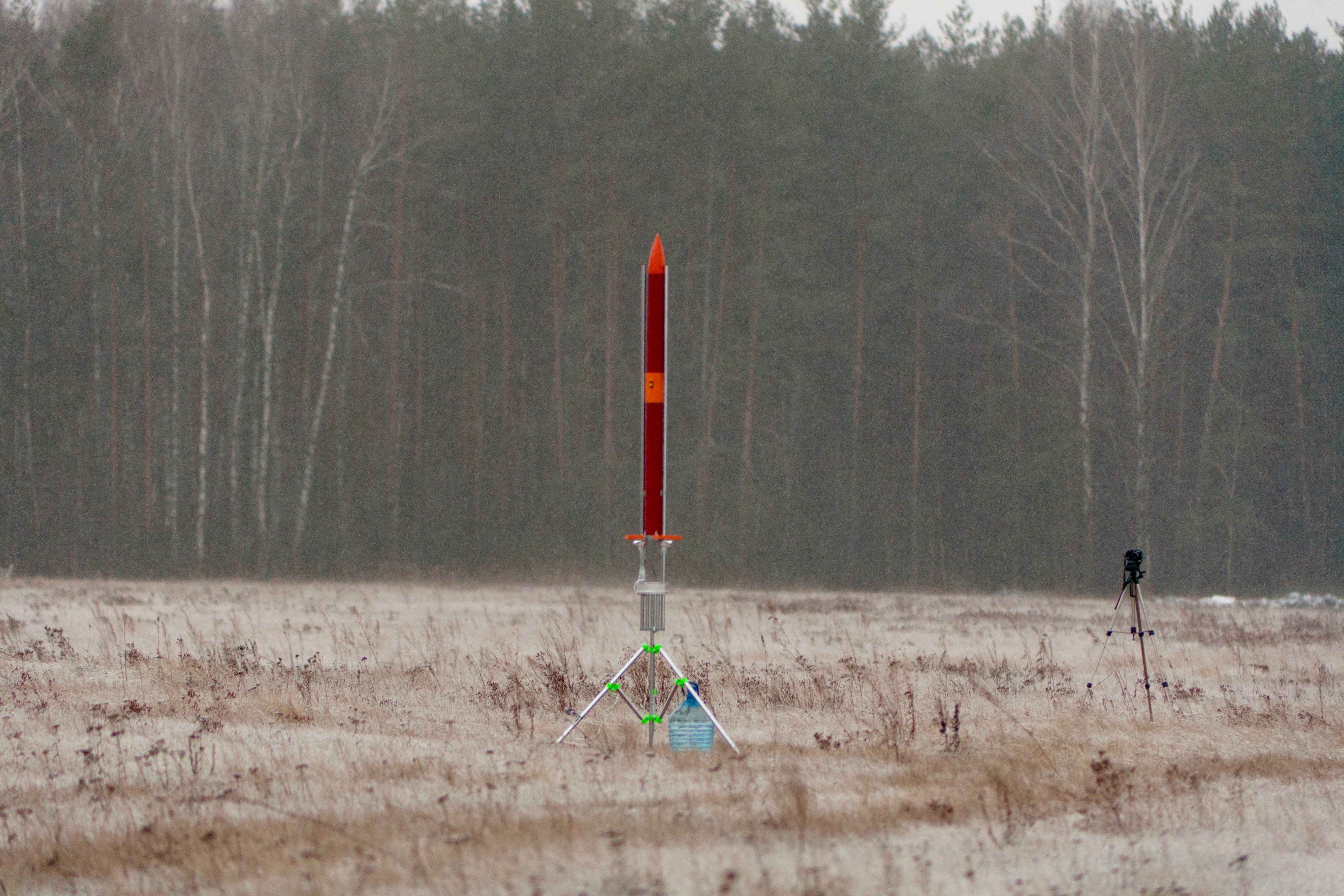
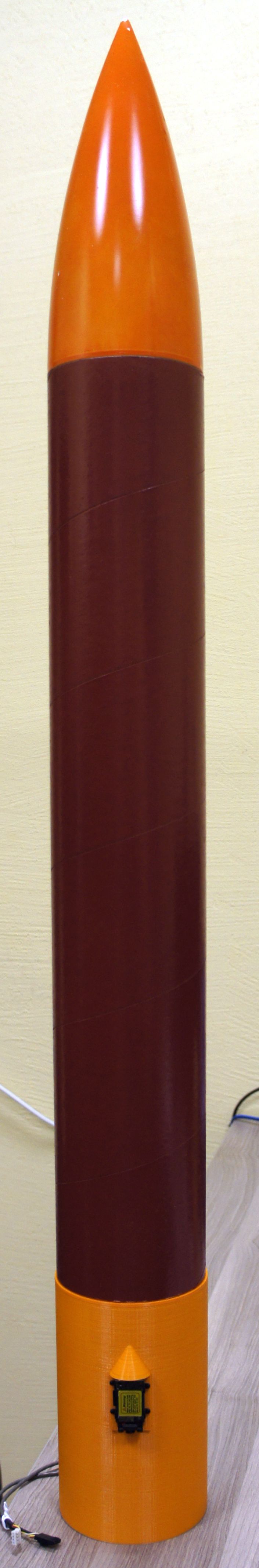
General view of the rocket on a launcher: