Flow tests of engine test stand
On Sunday, October 2 we conducted the final assembly and setup of the test stand for static firing. To receive and process sensor readings a monitoring & control board was conected and checked, strain gauges were adjusted and calibrated.
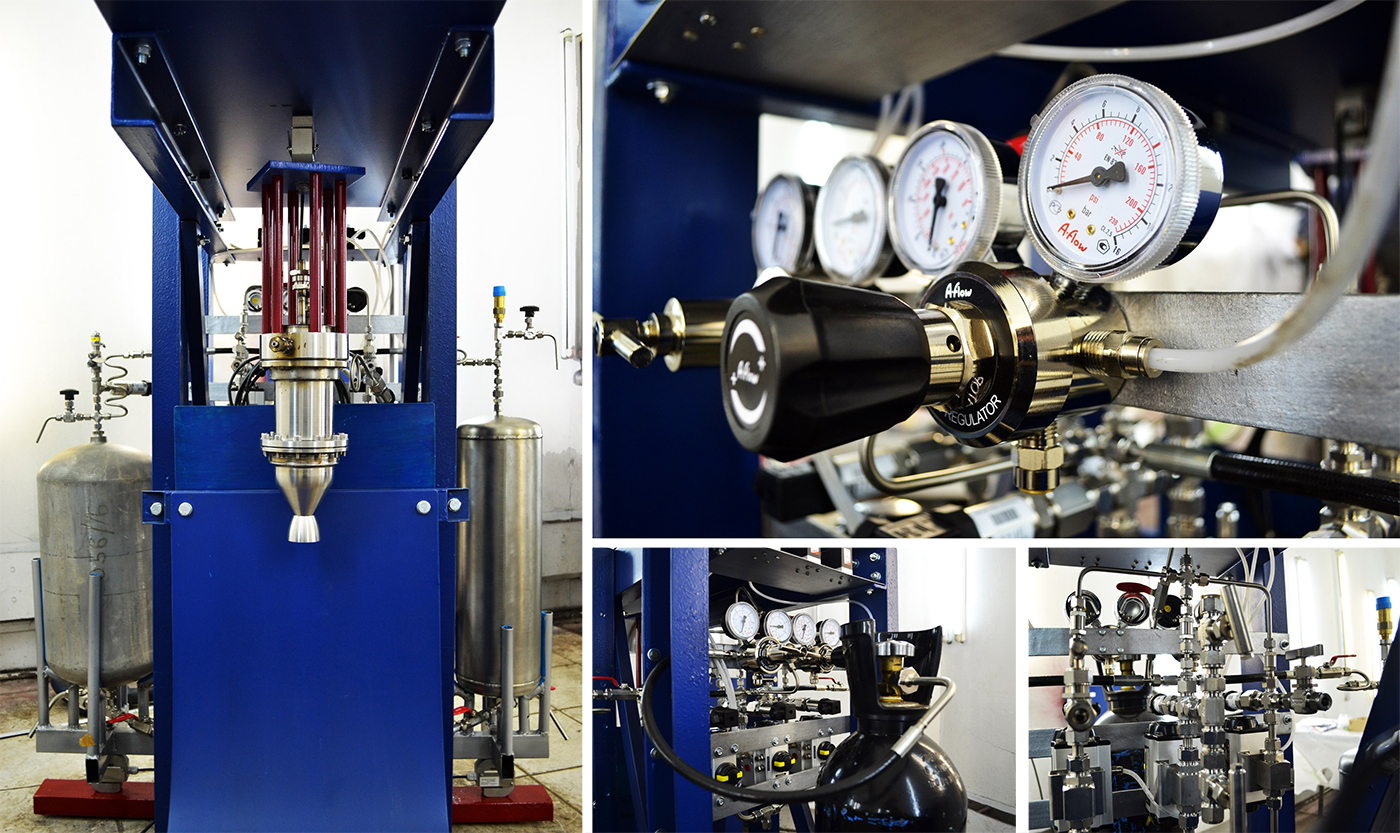
Besides, threaded joints were sealed, pipe joints were crimped and pressurization gas pipeline was upgraded for connecting larger volume cylinders.
First it was necessary to make waterflow tests to determine flow rates, perform leak checks and, of course, gain experience of work with feed system.
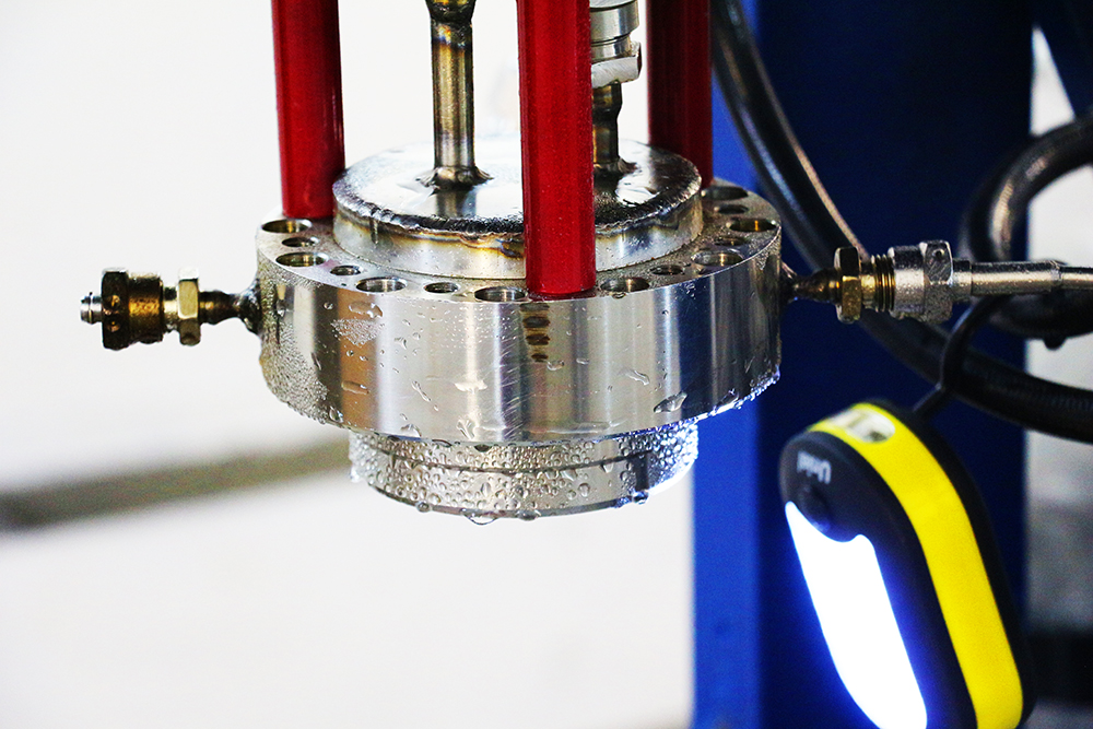
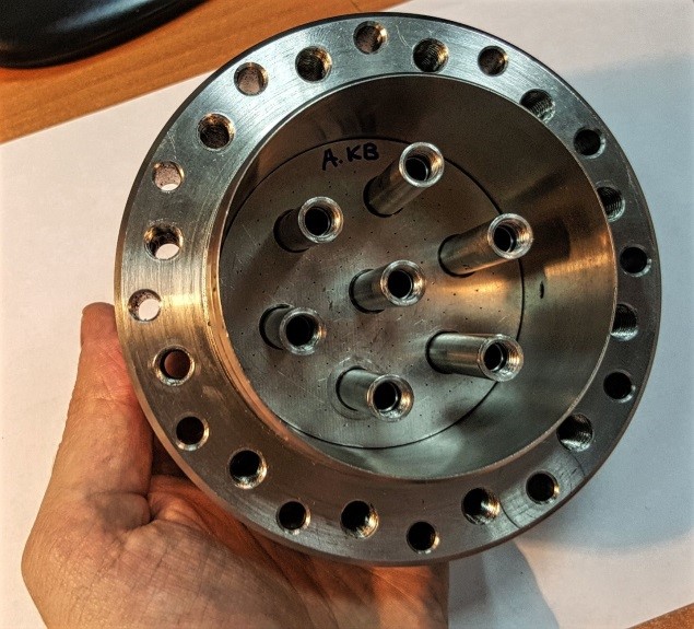
Injector head of the engine was mounted to the test stand. Cover of the catalyst pack section inside the injector head was removed. Data was recorded by a computer connected to the monitoring & control board. The process was traced by recording the output of strain gauges, and video was also recorded.
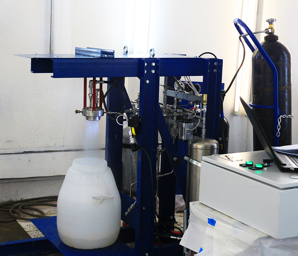
Flow tests of the injector head were conducted separately for each propellant line. There were four tests, two of which are for the oxidizer pipeline, and the other two are for the fuel pipeline. The corresponding tanks were filled with distilled water, then electric valve was opened and the flow rate was measured.
- First test of the oxidizer line: tank was filled with 4.5 liters of water, the flow control valve was fully opened, the flow rate was 0.56 l/sec.
- Second test of the oxidizer line: tank was filled with 6.8 liters of water, the flow control valve was half opened, the flow rate was 0.41 l/sec.
- First test of the fuel line: tank was filled with 3.9 liters of water, the flow control valve was fully opened, the flow rate was 0.12 l/sec.
- Second test of the fuel line: tank was filled with 4.1 liters of water, the flow control valve was half opened, the flow rate was 0.13 l/sec.
Measurement of the flow rate in the fuel pipeline needs to be improved using additional valve positions - the collected data are contrary to expectations.
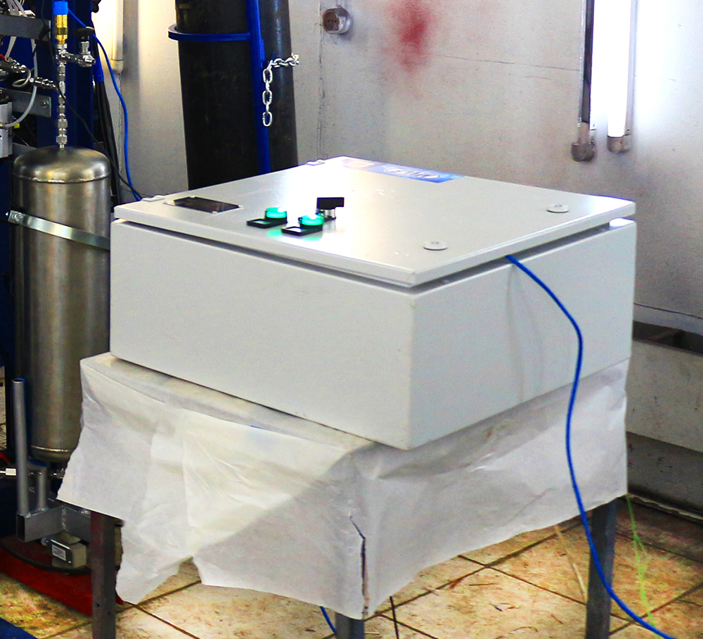
Monitoring & control board
As a result, we gained experience of work with test stand in safe environment, and made the conclusion that the following improvements are needed:
— add the capability to remotely control the pressurizing gas supply;
— improve the performance of monitoring software;
— make a control device for the propellant flow control valves.
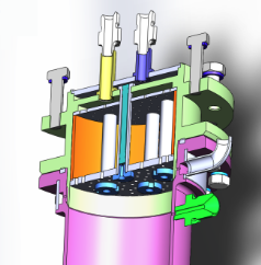
Cutaway view and the appearance of the engine catalyst pack section
After the series of waterflow tests we decided to test the engine with fluids almost identical to operating propellants. To test the catalyst operation in more harsh conditions we used hydrogen peroxide with lower concentration (58%) to safely perform the series of future static firing.
The rocket engine was assembled and mounted to the test stand, and metallic catalyst (Option B) was placed into the engine. Then propellant pipelines have been connected to the engine, and the procedure of fueling the propellant tanks started. Before that all taps and valves except safety valves have been closed.
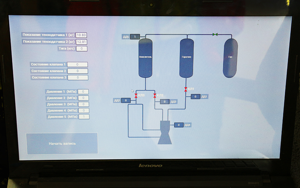
User interface of the monitoring & control board
Fueling was nominal, the software was activated for recording data from sensors of the feed system, and pressurizing gas supply valve was opened. All the staff left the room and further control was performed remotely.
Two flow tests were conducted, during which we used 2.85 kg of propellants. General sequence of the test is as follows:
- feeding the peroxide;
- observing a steam jet, buildup of pressure inside the injector head;
- feeding the kerosene;
- the jet gets brown due to the spray of kerosene;
- stopping the kerosene feed;
- stopping the peroxide feed.
Video of the stand testing
The tests have confirmed the operability of the test stand and engine components, and produced data close to estimated values for these specifications of propellants and environment. Injector head pressure was 5 bar, and measured thrust was 9.6 kgf. It has been found that the catalyst operates nominally, it actively decomposes hydrogen peroxide, while the injector head provides adequate spraying and mixing of propellants inside combustion chamber.
After making the series of necessary improvements we will prepare for static firing in the open air involving operating propellants.