Rocket engine with a thrust of 100 kgf is assembled and ready for testing
The first instance of our liquid-propellant rocket engine, powered by kerosene and high-test peroxide, is assembled and ready for firing on a test stand at MAI.
It all started about a year ago with the creation of 3D models and the release of design documentation.

We sent finished drawings to multiple contractors including ArtMech, our primary metalworking partner. All chamber related work was duplicated, and the manufacture of injectors was delegated to multiple suppliers. Unfortunately, here we encountered all the complexity of manufacturing seemingly simple metal parts.
Notably a lot of effort had to be spent on centripetal injectors designed to spray the fuel in chamber. On the cutaway view of 3D model they can be seen as blue cylinders, each with nut at one end. And this is how they look in metal (one of the injectors is shown with removed nut, a pencil is shown for scale):
We described the injector tests earlier. As a result, out of many dozens of injectors seven were selected. Kerosene will enter the chamber through them. Kerosene injectors are integrated in the upper part of the chamber, which serves as a gasifier for oxidizer — the area where the hydrogen peroxide passes through solid catalyst and decomposes into water vapor and oxygen. This gaseous mixture also enters the engine chamber.
To understand why the injector manufacturing caused such difficulties, we need to look inside — there is a screw-shaped swirler in the channel. That is the kerosene entering the injector not just smoothly flows down, but gets swirled. The screw-shaped swirler has many fine parts, and the manufacturing precision of their actual size determines the width of the gaps through which the kerosene flows and gets sprayed in the chamber. The range of possible outcomes is from "the fluid doesn't flow through the injector at all" to "it is sprayed uniformly in all directions". The ideal outcome - kerosene is sprayed downwards as a fine cone. Something like what is shown below:
So getting an ideal injector depends not only on the skills and integrity of the manufacturer, but also on the equipment used and finally on the fine motor skills of the specialist. Several series of tests for completed injectors at different pressures have allowed us to select the ones which have the spray cone close to ideal. Pictured below is a swirler which has not passed the selection.
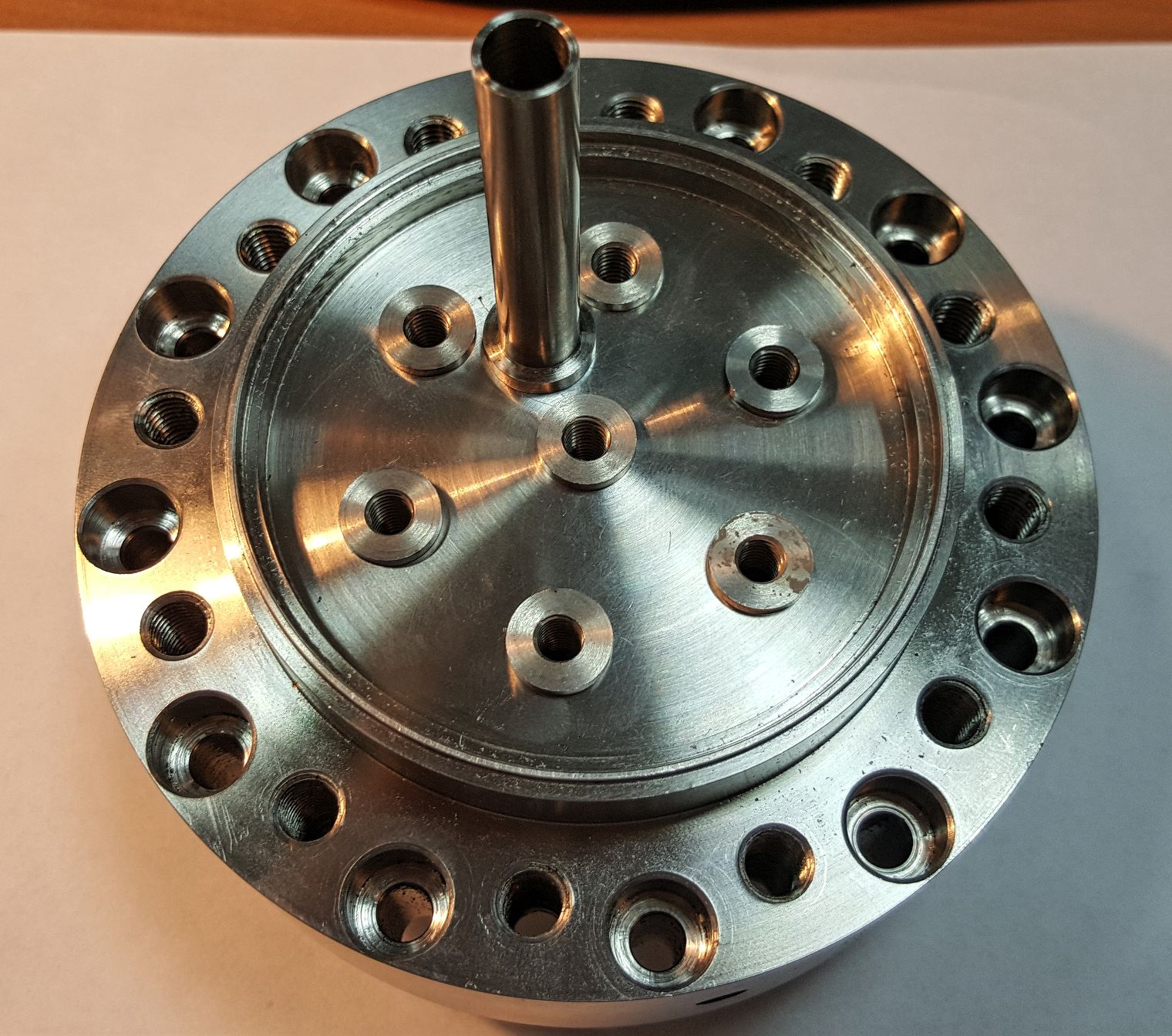
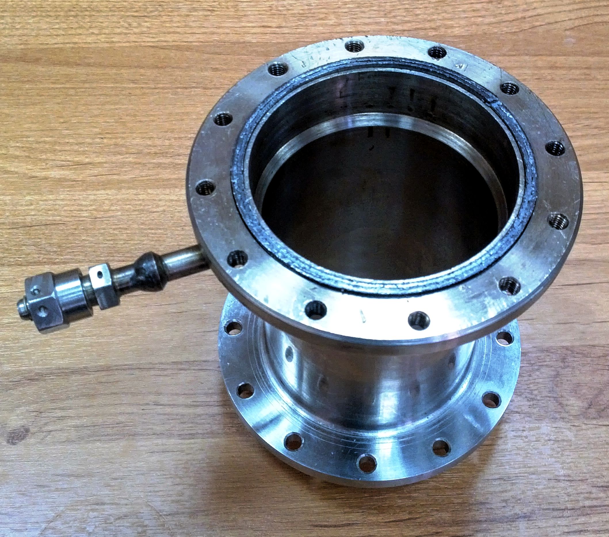
Let's see how our engine looks in metal. Here is the engine cover with pipelines for the inflow of peroxide and kerosene:
If the cover is removed, you can see that peroxide is fed through the long pipe while kerosene is fed through the short one. Then the kerosene is distributed over seven holes.
The gasifier is attached to the bottom of the cover. Let's look at the side facing the chamber.
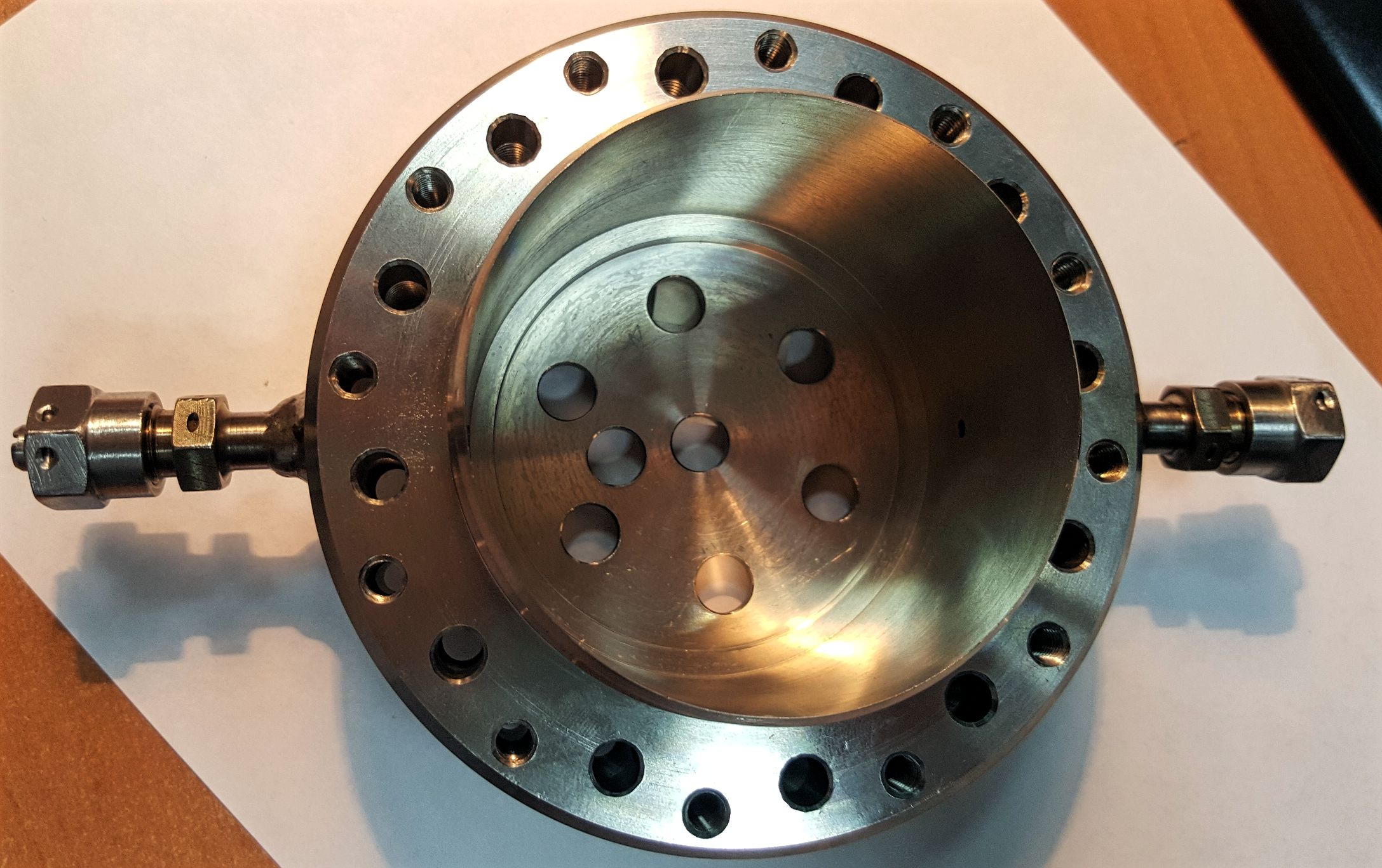
What looks from this point like the part's bottom is actually its upper section, and is to be connected to the cover of the engine. Kerosene will flow into the chamber through the seven holes, and peroxide will flow to the catalyst through the eighth hole (to the left of the center, the only unsymmetrical). To put it more precisely, it will not flow directly, but through a special plate with tiny holes, which distribute the flow evenly.
In the next photo this plate and kerosene injectors are inserted into the gasifier.
Almost entire free volume of the gasifier is to be occupied with solid catalyst, through which peroxide will flow. Kerosene will go through the injectors without mixing with peroxide.
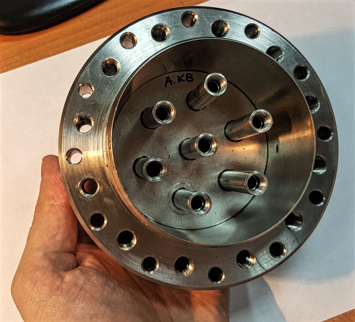
In the next photo the gasifier is closed by the plate facing the combustion chamber.
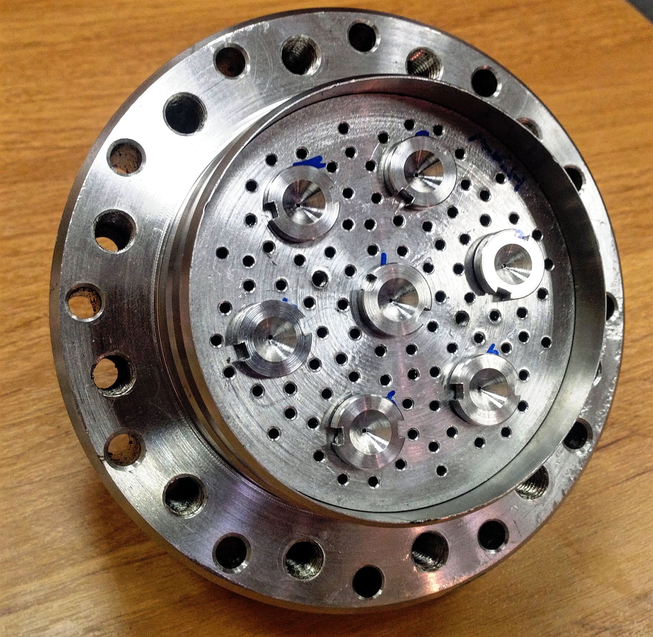
Kerosene will flow through the seven outlets (special nuts pictured above), while hot mixture of steam and oxygen, i.e. peroxide decomposed into oxygen and water vapor, will pass through the small holes.
Now let's get to where they will flow. And they will flow into combustion chamber which is a cylinder where kerosene ignites and burns in oxygen heated on catalyst.
Hot gases enter the nozzle, in which they are accelerated to high velocities. Here are different views of the nozzle. The nozzle includes large convergent (subsonic) section, followed by throat, and then divergent (supersonic) section.
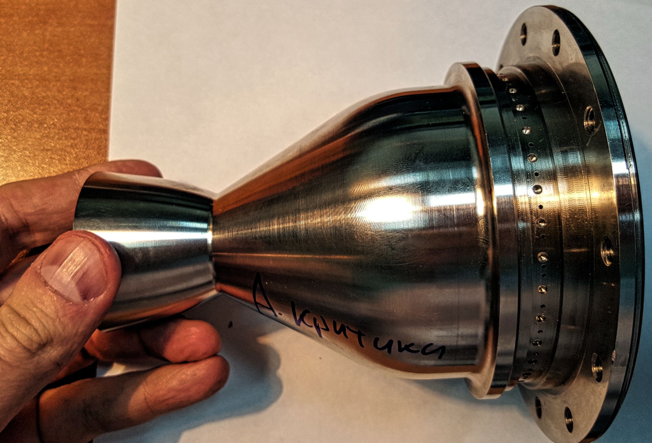
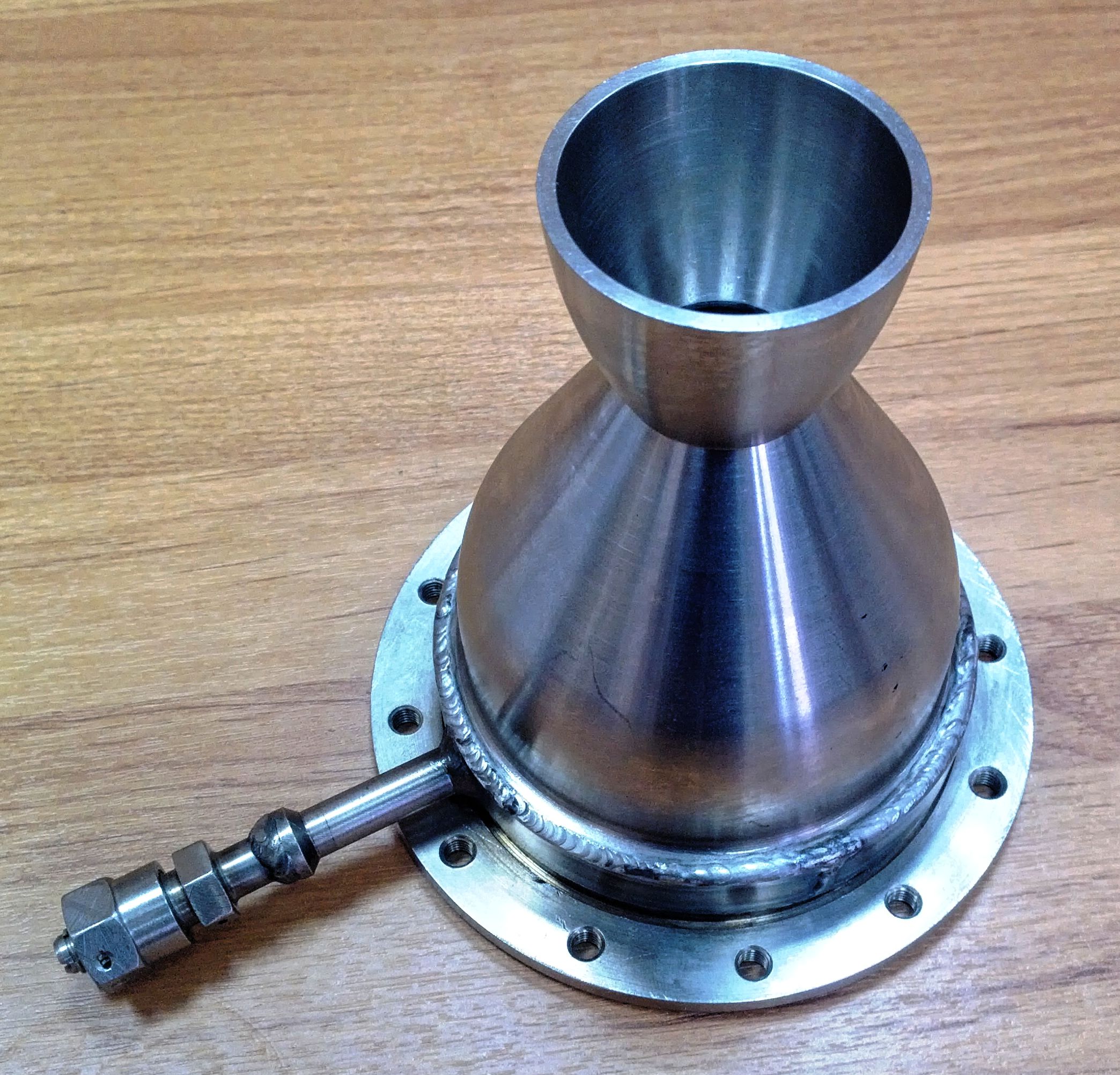
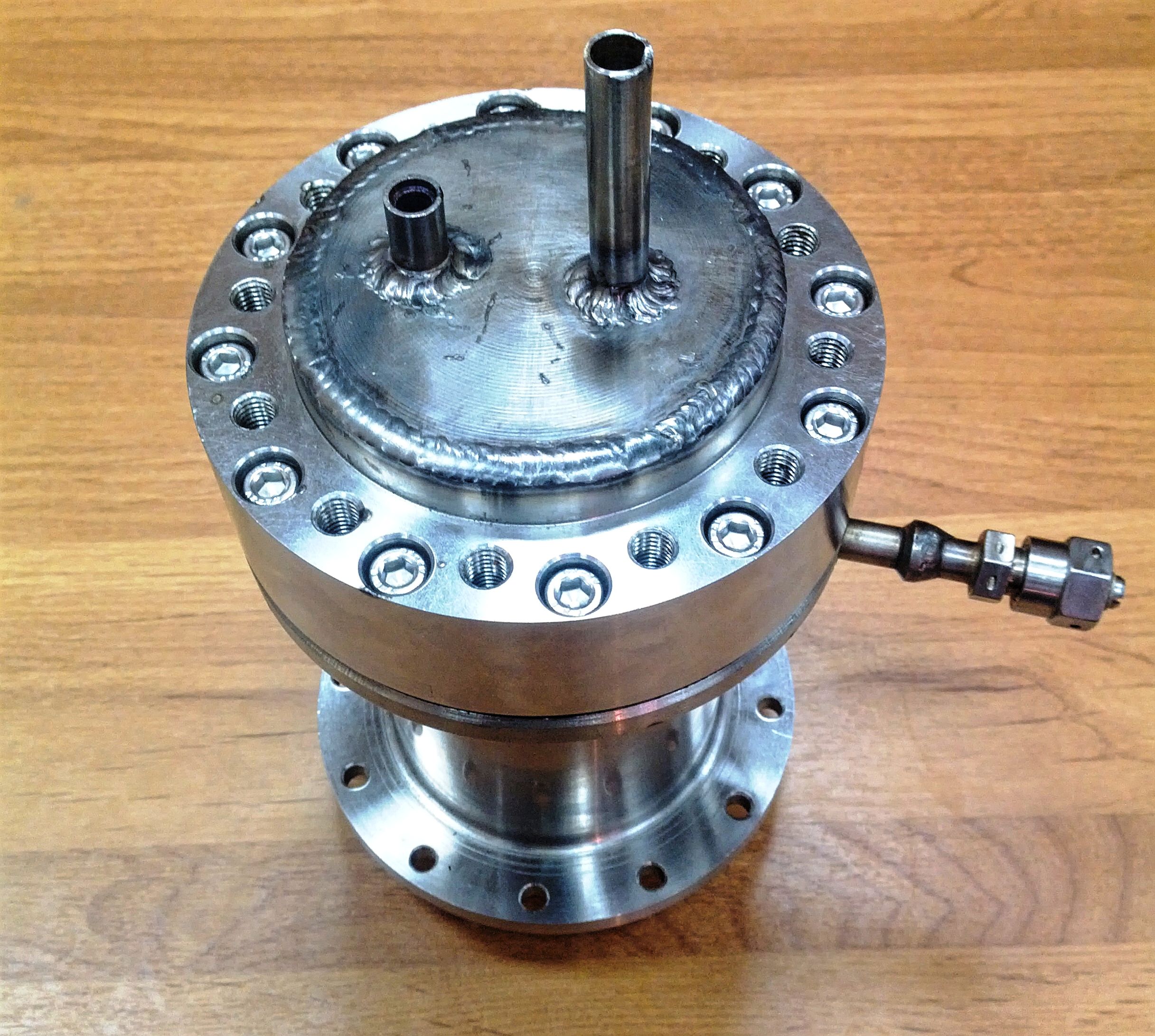
Finally, here is how the assembled engine looks:
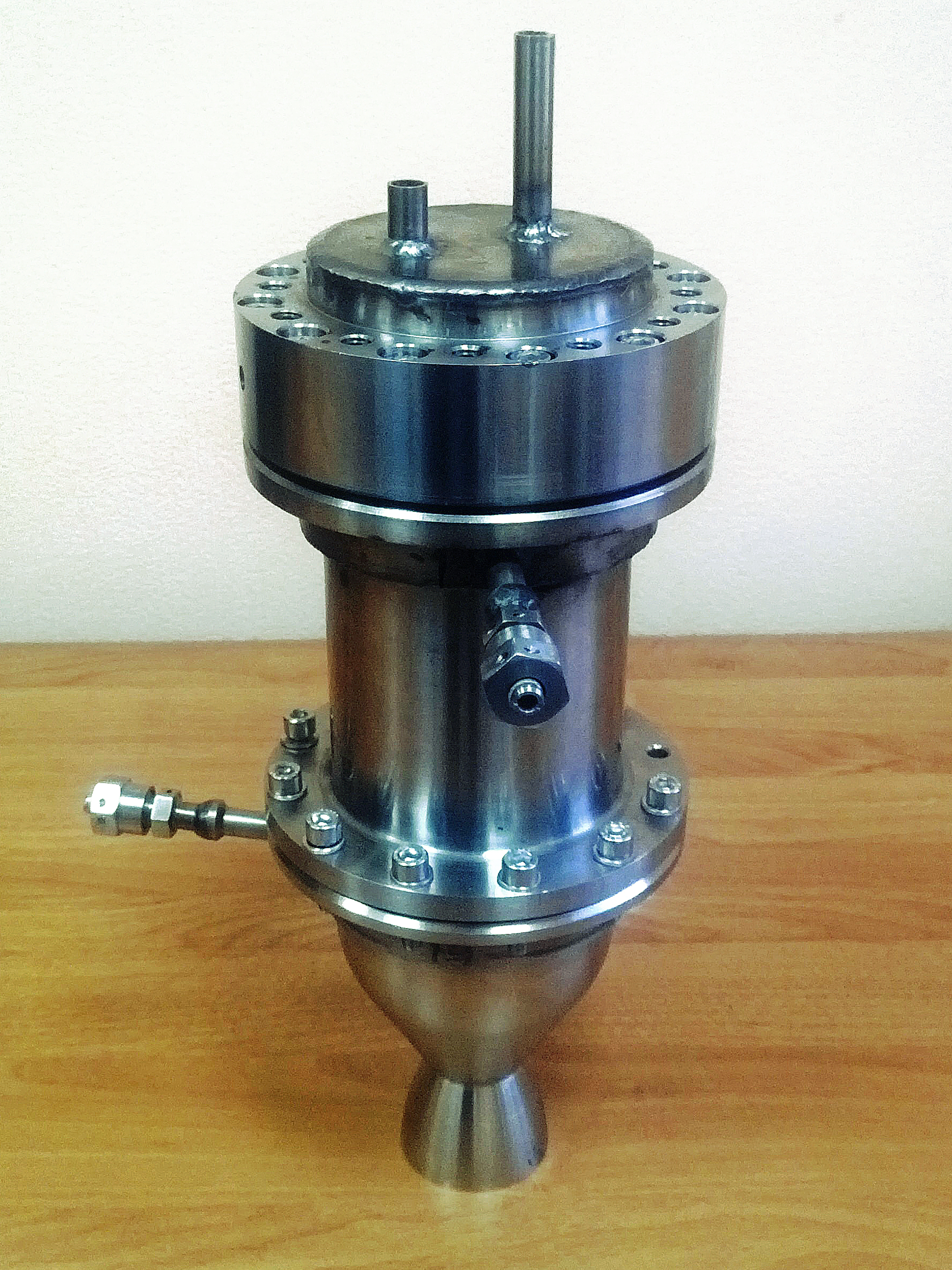
Beautiful, right?
We will make at least one more instance of this engine from stainless steel, then switch to making engines from Inconel.
A careful reader will ask: what these fittings on the sides of the engine for? Our engine has a curtain - fluid is injected along the walls of the chamber to prevent overheating of the chamber. In flight the curtain will be formed by peroxide or kerosene (to be determined from the test results) from the rocket tanks. During the test firings the curtain may be formed by kerosene, peroxide, water or nothing at all (for short tests). It's this curtain are the fittings for. Moreover, there are two curtains: one for cooling the chamber, and the other for subsonic section of the nozzle and for the nozzle throat.
If you are an engineer or just want to know more detail on the specifications and design of the engine, then the technical note below is for you.
* * *
The engine is designed for proving the basic design and technology solutions on a test stand. The test firings are expected in 2016.
The engine burns stable high-boiling propellants. Estimated thrust at sea level — 100 kgf, in vacuum — 120 kgf; estimated specific impulse at sea level — 1840 m/s, in vacuum — 2200 m/s; estimated weight-to-thrust ratio — 0.040 kg/kgf. Actual specifications of the engine will be refined during the tests.
The rocket engine consists of one chamber, set of automation system assemblies, units and parts of general assembly.
The engine is mounted directly to bearing structure of the stand through the flange at the top of the chamber.
Primary specifications of the engine
propellants:
- oxidizer — PV-85 (stabilized high-test peroxide, 85%)
- fuel — TS-1 (jet fuel grade)
thrust, kgf:
- at sea level — 100.0
- in vacuum — 120.0
specific impulse, m/s:
- at sea level — 1840
- in vacuum — 2200
flow rate, kg/s:
- oxidizer — 0.476
- fuel — 0.057
propellant mixture ratio (O:F) — 8.43:1
oxidizer excess ratio — 1.00
gas pressure, bar:
- in combustion chamber — 16
- at nozzle exit — 0.7
mass of the combustion chamber, kg — 4.0
inner diameter of the engine, mm:
- cylindrical section — 80.0
- at nozzle exit — 44.3
The engine is an assembly of injector section with integrated gasifier for oxidizer, cylindrical combustion chamber and shaped nozzle. The chamber components have flanges and are connected together by bolts.
The injector section has 88 single-propellant jet injectors for oxidizer and 7 single-propellant centripetal injectors for fuel. The injectors are arranged in concentric circles. Each fuel injector is surrounded by ten jet injectors of oxidizer, and remaining jet injectors of oxidizer are placed on the unoccupied area of the plate.
The chamber has internal two-stage cooling by fluid (fuel or oxidizer, to be determined from the test results) entering the chamber through two curtain belts — upper and lower. The upper belt is at the top of the chamber cylindrical section, it provides cooling to the chamber cylindrical section. The lower one is at the beginning of subsonic section of the nozzle, it provides cooling to the subsonic section and the nozzle throat.
The engine is powered by hypergolic propellants. During the engine start sequence the oxidizer gets into the chamber earlier. On decomposition of the oxidizer in the gasifier its temperature reaches 900 K, being significantly higher than TS-1 fuel autoignition temperature in the air (500 K). The fuel, injected into the hot oxidizer atmosphere of the chamber, ignites, and the combustion process becomes self-sustaining.
The gasifier for oxidizer operates on the principle of catalytic decomposition of high-test peroxide in the presence of solid catalyst. The hot gas mixture created by hydrogen peroxide decomposition (water vapor and gaseous oxygen), being an oxidizer, enters the combustion chamber.
Primary specifications of the gas generator
propellants:
- stabilized hydrogen peroxide (mass concentration), % — 85±0.5
hydrogen peroxide flow rate, kg/s — 0.476
specific catalyst load, (hydrogen peroxide, kg/s)/(catalyst, kg) — 3.0
continuous operation time, at least, s — 150
parameters of the gas mixture at the gasifier exit:
- pressure, bar — 16
- temperature, K — 900
The gasifier is integrated in the injector section. Its cylinder, inner and middle bottoms enclose the gasifier chamber. The bottoms are connected together by the fuel injectors. The distance between the bottoms is determined by the height of the cylinder. The volume around the fuel injectors is filled with solid catalyst.